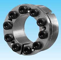
>> TSUBAKI POWER - LOCK KE Series
Features
-
Range of Size Available
Available in a variety of size for smaller motors or sensors.
-
Wide Tolerance for Shafts
POWER-LOCK KE Series is designed with a slit construction and special taper angle to cover a wider tolerance of shaft szies, such as motor shafts.
-
Self - Centering
-
Compact Construction
Compact design is possible, because the ratio of inside and outside diameter is small.


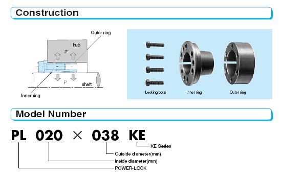
Model Number |
Dimensions (mm) |
Transmissible Torque |
Transmissible Thrust |
Contact Pressure (MPa) |
Locking Bolts |
Mass |
|||||||||||||
d x D Inside Dia Outside Dia |
L2 |
L |
Lt |
d1 |
D1 |
Mt |
Pax |
Shaft P |
Hub bore P' |
Qty. |
Size |
Tightening Torque Ma |
|||||||
N-m |
{kgf-m} |
kN |
{kgf} |
MPa |
{kgf/mm2} |
MPa |
{kgf/mm2} |
N.m |
{kgf.m} |
(kg) |
|||||||||
PL005x 016KE |
8 |
12 |
13.5 |
16.5 |
11.5 |
18.5 |
7.5 |
{ 0.77} |
2.86 |
{292} |
223 |
{22.8} |
70 |
{7.1} |
3 |
M3x10 |
1.9 |
{0.19} |
0.02 |
PL006x 017KE |
8 |
12 |
13.5 |
16.5 |
12.5 |
19.5 |
9.0 |
{0.92} |
2.86 |
{292} |
186 |
{19.0} |
66 |
{6.7} |
3 |
M3x10 |
1.9 |
{0.19} |
0.02 |
PL008x 021KE |
10 |
14.5 |
16.5 |
20.5 |
15.6 |
23.5 |
24.5 |
{2.5} |
5.96 |
{608} |
232 |
{23.7} |
88 |
{9.0} |
3 |
M4x12 |
4.8 |
{0.49} |
0.03 |
PL010x 23KE |
10 |
14.5 |
16.5 |
20.5 |
17.6 |
25.5 |
31.4 |
{3.2} |
5.96 |
{608} |
186 |
{19.0} |
80 |
{8.2} |
3 |
M4x12 |
4.8 |
{0.49} |
0.04 |
PL011x024KE |
10 |
14.5 |
16.5 |
20.5 |
18.6 |
26.5 |
34.3 |
{3..5} |
5.96 |
{608} |
169 |
{17.2} |
70 |
{7.9} |
3 |
M4x12 |
4.8 |
{0.49} |
0.04 |
PL012x026KE |
10 |
14.5 |
16.5 |
20.5 |
20 |
28.5 |
50.0 |
{5.1} |
7.94 |
{810} |
207 |
{21.1} |
95 |
{9.7} |
4 |
M4x12 |
4.8 |
{0.49} |
0.05 |
PL014x028KE |
12 |
17.5 |
20 |
24 |
22 |
30.5 |
73.5 |
{7.5} |
9.90 |
{1010} |
184 |
{18.8} |
92 |
{9.4} |
5 |
M4x14 |
4.8 |
{0.49} |
0.06 |
PL015x029KE |
12 |
17.5 |
20 |
24 |
23 |
31.5 |
94.1 |
{9.6} |
11.9 |
{1210} |
207 |
{21.1} |
107 |
{10.9} |
6 |
M4x14 |
4.8 |
{0.49} |
0.07 |
PL016x030KE |
12 |
17.5 |
20 |
24 |
24 |
32.5 |
101 |
{10.3} |
11.9 |
{1210} |
194 |
{19.8} |
103 |
{10.5} |
6 |
M4x14 |
4.8 |
{0.49} |
0.07 |
PL 017x031KE |
12 |
17.5 |
20 |
24 |
25 |
33.5 |
107 |
{10.9} |
11.9 |
{1210} |
182 |
{18.6} |
100 |
{10.2} |
6 |
M4x14 |
4.8 |
{0.49} |
0.07 |
PL018 x032KE |
12 |
17.5 |
20 |
24 |
26 |
34.5 |
113 |
{11.5} |
11.9 |
{1210} |
172 |
{17.6} |
97 |
{9.9} |
6 |
M4x14 |
4.8 |
{0.49} |
0.08 |
PL 019x033KE |
12 |
17.5 |
20 |
24 |
27 |
35.5 |
120 |
{12.2} |
11.9 |
{1210} |
163 |
{16.6} |
94 |
{9.6} |
6 |
M4x14 |
4.8 |
{0.49} |
0.08 |
PL 020x038KE |
15 |
20.5 |
25 |
30 |
30 |
42 |
206 |
{21.0} |
19.4 |
{1980} |
203 |
{20.7} |
107 |
{10.9} |
6 |
M5x18 |
9.8 |
{1.0} |
0.14 |
PL 022x040KE |
15 |
20.5 |
25 |
30 |
32 |
44 |
226 |
{23.1} |
19.4 |
{1980} |
184 |
{18.8} |
101 |
{10.3} |
6 |
M5x18 |
9.8 |
{1.0} |
0.15 |
PL024x042KE |
15 |
20.5 |
25 |
30 |
34 |
46 |
329 |
{33.6} |
25.9 |
{2640} |
225 |
{23.0} |
128 |
{13.1} |
8 |
M5x18 |
9.8 |
{1.0} |
0.16 |
PL025x043KE |
15 |
20.5 |
25 |
30 |
35 |
47 |
343 |
{35.0} |
25.9 |
{2640} |
216 |
{22.0} |
125 |
{12.8} |
8 |
M5x18 |
9.8 |
{1.0} |
0.17 |
PL 028x046KE |
17 |
22.5 |
28 |
33 |
38.5 |
50 |
432 |
{44.1} |
29.2 |
{2980} |
191 |
{19.5} |
117 |
{11.9} |
9 |
M5x18 |
9.8 |
{1.0} |
0.21 |
PL030x048KE |
17 |
22.5 |
28 |
33 |
40.5 |
52 |
515 |
{52.5} |
32.4 |
{3310} |
199 |
{20.3} |
124 |
{12.7} |
10 |
M5x18 |
9.8 |
{1.0} |
0.22 |
PL032x050KE |
17 |
22.5 |
28 |
33 |
42.5 |
54 |
549 |
{56.0} |
32.4 |
{3310} |
186 |
{19.0} |
120 |
{12.2} |
10 |
M5x18 |
9.8 |
{1.0} |
0.23 |
PL035x057KE |
19 |
25 |
32 |
38 |
47.5 |
62 |
678 |
{69.2} |
36.6 |
{3730} |
172 |
{17.5} |
106 |
{10.8} |
8 |
M6x22 |
16.7 |
{1.7} |
0.36 |
PL038x060KE |
19 |
25 |
32 |
38 |
50.5 |
65 |
921 |
{94.0} |
45.8 |
{4670} |
198 |
{20.2} |
125 |
{12.8} |
10 |
M6x22 |
16.7 |
{1.7} |
0.39 |
PL040x062KE |
19 |
25 |
32 |
38 |
52.5 |
67 |
969 |
{98.9} |
45.8 |
{4670} |
188 |
{19.2} |
122 |
{12.4} |
10 |
M6x22 |
16.7 |
{1.7} |
0.40 |
PL042x064KE |
19 |
25 |
32 |
38 |
54.5 |
69 |
1010 |
{103} |
45.8 |
{4670} |
179 |
{18.3} |
118 |
{12.0} |
10 |
M6x22 |
16.7 |
{1.7} |
0.42 |
PL045x067KE |
19 |
25 |
32 |
38 |
57.5 |
72 |
1090 |
{111} |
45.8 |
{4670} |
168 |
{17.1} |
113 |
{11.5} |
10 |
M6x22 |
16.7 |
{1.7} |
0.44 |
PL048x070KE |
19 |
25 |
32 |
38 |
60.5 |
75 |
1390 |
{142} |
54.9 |
{5600} |
188 |
{19.2} |
129 |
{13.2} |
12 |
M6x22 |
16.7 |
{1.7} |
0.46 |
PL050x072KE |
19 |
26 |
34.5 |
40.5 |
63.5 |
77 |
1700 |
{173} |
64.1 |
{6540} |
211 |
{21.5} |
146 |
{14.9} |
14 |
M6x25 |
16.7 |
{1.7} |
0.50 |
PL055x077KE |
19 |
26 |
34.5 |
40.5 |
67.5 |
82 |
1860 |
{190} |
64.1 |
{6540} |
191 |
{19.5} |
137 |
{14.0} |
14 |
M6x25 |
16.7 |
{1.7} |
0.55 |
PL060x082KE |
19 |
26 |
34.5 |
40.5 |
72.5 |
87 |
2180 |
{222} |
68.6 |
{7000} |
188 |
{19.2} |
137 |
{14.0} |
15 |
M6x25 |
16.7 |
{1.7} |
0.59 |
PL065x087KE |
19 |
26 |
34.5 |
40.5 |
77.5 |
92 |
2360 |
{241} |
68.6 |
{7000} |
173 |
{17.7} |
129 |
{13.2} |
15 |
M6x25 |
16.7 |
{1.7} |
0.63 |
PL070x097KE |
22 |
31.5 |
40.5 |
48.5 |
85.5 |
102 |
3750 |
{383} |
101 |
{10300} |
206 |
{21.0} |
148 |
{15.1} |
12 |
M6x25 |
40.2 |
{4.1} |
0.99 |
PL075x102KE |
22 |
31.5 |
40.5 |
48.5 |
90.5 |
107 |
4030 |
{411} |
101 |
{10300} |
192 |
{19.6} |
141 |
{14.1} |
12 |
M8x30 |
40.2 |
{4.1} |
1.05 |
PL080x107KE |
22 |
31.5 |
41.5 |
49.5 |
95.5 |
112 |
5010 |
{511} |
118 |
{12000} |
210 |
{21.4} |
157 |
{16.0} |
14 |
M8x30 |
40.2 |
{4.1} |
1.14 |
PL085x112KE |
22 |
31.5 |
41.5 |
49.5 |
100.5 |
117 |
5320 |
{543} |
118 |
{12000} |
198 |
{20.2} |
150 |
{15.3} |
14 |
M8x30 |
40.2 |
{4.1} |
1.20 |
PL090x123KE |
29 |
41.5 |
54 |
64 |
109.5 |
128 |
8960 |
{914} |
187 |
{19100} |
224 |
{22.9} |
165 |
{16.8} |
14 |
M10x40 |
81.3 |
{8.3} |
2.08 |
PL095x128KE |
29 |
41.5 |
54 |
64 |
114.5 |
133 |
9460 |
{965} |
187 |
{19100} |
213 |
{21.7} |
158 |
{16.1} |
14 |
M10x40 |
81.3 |
{8.3} |
2.18 |
PL100x133KE |
29 |
41.5 |
54 |
64 |
119.5 |
138 |
9900 |
{1010} |
187 |
{19100} |
203 |
{20.7} |
152 |
{15.5} |
14 |
M10x40 |
81.3 |
{8.3} |
2.28 |
Note :-
- Torque Mt in above table is shown in case of Pax =0 and thrust is shown in case of Mt =0. When torque and thrust are applied, calculate composite torque and compare it with Mt.
-
Contact pressure P and P' in the above table indicate mean value only.
These pressures will fluctuate from - 20% to +40% due to the variable friction component forces resulting from the locking bolts. Mt and Pax are calculated as minimum values.
