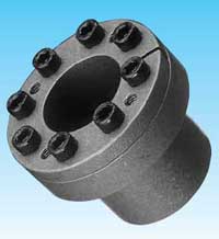
>> TSUBAKI POWER - LOCK TF Series
Features
-
Small-diameter hub can be connected
POWER-LOCK TF is designed for small diameter hub. Outside diameter of POWER-LOCK and contact pressure in the hub bore are small.
-
Self- Centering
The TF Series has excellent centering function Pre-centering (guide) is not required.
-
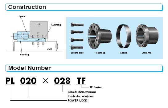
Simple construction


Model Number |
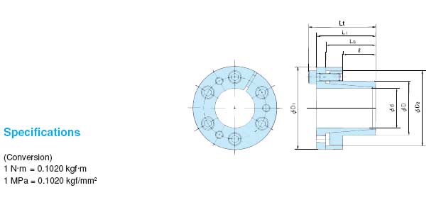
Dimensions (mm) |
Transmissible Torque |
Transmissible Thrust |
Contact Pressure |
Locking Bolts |
Mass |
|||||||||||||
d x D Inside Dia Outside Dia |
Mt |
Pax |
Shaft P |
Hub bore P' |
Qty |
Size |
Tightening Torque Ma |
||||||||||||
L0 |
L1 |
Lt |
D1 |
D2 |
N-m |
{kgf.m} |
kN |
{kgf} |
MPa |
{kgf/mm2} |
MPa |
{kgf/mm2} |
N.m |
{kgf.m} |
(kg) |
||||
PL006x012TF |
10 |
19 |
21 |
24 |
25 |
23.0 |
11 |
{1.2} |
3.78 |
{386} |
186 |
{19.0} |
93 |
{9.5} |
3 |
M3 x 10 |
2.25 |
{0.23} |
0.05 |
PL008x015 TF |
12 |
22 |
25 |
29 |
27 |
24.0 |
26 |
{2.7} |
6.53 |
{666} |
200 |
{20.4} |
107 |
{10.9} |
3 |
M4 x 10 |
4.80 |
{0.49} |
0.07 |
PL010x018TF |
14 |
23 |
26 |
30 |
32 |
28.0 |
44 |
{4.4} |
8.70 |
{888} |
183 |
{18.7} |
102 |
{10.4} |
4 |
M4 x 10 |
4.80 |
{0.49} |
0.09 |
PL011x018TF |
14 |
23 |
26 |
30 |
32 |
28.0 |
48 |
{4.9} |
8.70 |
{888} |
167 |
{17.0} |
102 |
{10.4} |
4 |
M4 x 10 |
4.80 |
{0.49} |
0.08 |
PL012x020TF |
14 |
23 |
26 |
30 |
34 |
30.0 |
52 |
{5.3} |
8.70 |
{888} |
153 |
{15.6} |
92 |
{9.3} |
4 |
M4 x 10 |
4.80 |
{0.49} |
0.10 |
PL014x022TF |
14 |
23 |
26 |
30 |
38 |
33.0 |
61 |
{6.2} |
8.70 |
{888} |
131 |
{13.4} |
83 |
{8.5} |
4 |
M4 x 10 |
4.80 |
{0.49} |
0.12 |
PL015x023TF |
14 |
24 |
30 |
35 |
39 |
35.5 |
107 |
{10.9} |
14.2 |
{1450} |
199 |
{20.4} |
130 |
{13.3} |
4 |
M5 x 14 |
9.80 |
{1.00} |
0.15 |
PL016x024TF |
14 |
24 |
30 |
35 |
40 |
36.5 |
114 |
{11.6} |
14.2 |
{1450} |
187 |
{19.1} |
125 |
{12.7} |
4 |
M5 x 14 |
9.80 |
{1.00} |
0.16 |
PL018x026TF |
18 |
31 |
38 |
44 |
47 |
42 |
196 |
{20} |
21.6 |
{2200} |
217 |
{22.1} |
126 |
{12.9} |
4 |
M6 x 18 |
16.7 |
{1.70} |
0.27 |
PL019x027TF |
18 |
31 |
38 |
44 |
49 |
43 |
206 |
{21} |
21.6 |
{2200} |
205 |
{20.9} |
122 |
{12.4} |
4 |
M6 x 18 |
16.7 |
{1.70} |
0.29 |
PL020x028TF |
18 |
31 |
38 |
44 |
50 |
44 |
216 |
{22} |
21.6 |
{2200} |
195 |
{19.9} |
118 |
{12.0} |
4 |
M6 x 18 |
16.7 |
{1.70} |
0.30 |
PL022x032TF |
25 |
38 |
45 |
51 |
54 |
48 |
245 |
{25} |
21.6 |
{2200} |
121 |
{12.3} |
74 |
{7.5} |
4 |
M6 x 18 |
16.7 |
{1.70} |
0.38 |
PL024x034TF |
25 |
38 |
45 |
51 |
56 |
50 |
265 |
{27} |
21.6 |
{2200} |
111 |
{11.3} |
70 |
{7.1} |
4 |
M6 x 18 |
16.7 |
{1.70} |
0.41 |
PL025x034TF |
25 |
38 |
45 |
51 |
56 |
50 |
274 |
{28} |
21.6 |
{2200} |
107 |
{10.9} |
70 |
{7.1} |
4 |
M6 x 18 |
16.7 |
{1.70} |
0.39 |
PL028x039TF |
25 |
38 |
45 |
51 |
61 |
55 |
461 |
{47} |
32.3 |
{3300} |
142 |
{14.5} |
91 |
{9.3} |
6 |
M6 x 18 |
16.7 |
{1.70} |
0.47 |
PL030x041TF |
25 |
38 |
45 |
51 |
62 |
57 |
500 |
{51} |
32.3 |
{3300} |
133 |
{13.6} |
86 |
{8.8} |
6 |
M6 x 18 |
16.7 |
{1.70} |
0.48 |
PL032x043FT |
25 |
38 |
45 |
51 |
65 |
59 |
529 |
{54} |
32.3 |
{3300} |
124 |
{12.7} |
82 |
{8.4} |
6 |
M6 x 18 |
16.7 |
{1.70} |
0.52 |
PL035x047FT |
32 |
45 |
52 |
58 |
69 |
62 |
774 |
{79} |
44.1 |
{4500} |
116 |
{11.8} |
78 |
{8.0} |
8 |
M6 x 18 |
16.7 |
{1.70} |
0.63 |
PL038x050FT |
32 |
45 |
52 |
58 |
72 |
66 |
843 |
{86} |
44.1 |
{4500} |
107 |
{10.9} |
74 |
{7.5} |
8 |
M6 x 18 |
16.7 |
{1.70} |
0.67 |
PL040x053TF |
32 |
45 |
52 |
58 |
75 |
69 |
882 |
{90} |
44.1 |
{4500} |
101 |
{10.3} |
70 |
{7.1} |
8 |
M6 x 18 |
16.7 |
{1.70} |
0.73 |
PL042x055FT |
32 |
45 |
52 |
58 |
78 |
71 |
931 |
{95} |
44.1 |
{4500} |
96 |
{9.8} |
68 |
{6.9} |
8 |
M6 x 18 |
16.7 |
{1.70} |
0.78 |
PL045x059FT |
45 |
62 |
70 |
78 |
86 |
80 |
1850 |
{189} |
82.3 |
{8400} |
119 |
{12.1} |
82 |
{8.4} |
8 |
M8 x 22 |
40.2 |
{4.10} |
1.23 |
PL048x062FT |
45 |
62 |
70 |
78 |
87 |
81 |
1970 |
{201} |
82.3 |
{8400} |
111 |
{11.3} |
78 |
{8.0} |
8 |
M8 x 22 |
40.2 |
{4.10} |
1.24 |
PL050x065FT |
45 |
62 |
70 |
78 |
92 |
86 |
2060 |
{210} |
82.3 |
{8400} |
107 |
{10.9} |
74 |
{7.6} |
8 |
M8 x 22 |
40.2 |
{4.10} |
1.40 |
PL055x071FT |
55 |
72 |
80 |
88 |
98 |
92 |
2550 |
{260} |
92.1 |
{9400} |
87 |
{8.9} |
63 |
{6.4} |
9 |
M8 x 22 |
40.2 |
{4.10} |
1.70 |
PL060x077FT |
55 |
72 |
80 |
88 |
104 |
98 |
2770 |
{283} |
92.1 |
{9400} |
80 |
{8.2} |
58 |
{5.9} |
9 |
M8 x 22 |
40.2 |
{4.10} |
1.90 |
PL065x084FT |
55 |
72 |
80 |
88 |
111 |
105 |
3010 |
{307} |
92.1 |
{9400} |
74 |
{7.6} |
53 |
{5.4} |
9 |
M8 x 22 |
40.2 |
{4.10} |
2.21 |
PL070x090FT |
65 |
86 |
96 |
106 |
1198 |
113 |
5150 |
{525} |
147 |
{15000} |
92 |
{9.4} |
67 |
{6.8} |
9 |
M10 x 25 |
81.3 |
{8.30} |
3.05 |
PL075x095TF |
65 |
86 |
96 |
106 |
126 |
119 |
5490 |
{560} |
147 |
{15000} |
86 |
{8.8} |
63 |
{6.4} |
9 |
M10 x 25 |
81.3 |
{8.30} |
3.32 |
PL080x100TF |
65 |
86 |
96 |
106 |
131 |
125 |
7840 |
{800} |
196 |
{20000} |
108 |
{11.0} |
79 |
{8.1} |
12 |
M10 x 25 |
81.3 |
{8.30} |
3.50 |
PL085x106TF |
65 |
86 |
96 |
106 |
137 |
131 |
8330 |
{850} |
196 |
{20000} |
101 |
{10.3} |
75 |
{7.7} |
12 |
M10 x 25 |
81.3 |
{8.30} |
3.81 |
PL090x112TF |
65 |
86 |
96 |
106 |
144 |
137 |
8820 |
{900} |
196 |
{20000} |
96 |
{9.8} |
72 |
{7.3} |
12 |
M10 x 25 |
81.3 |
{8.30} |
4.20 |
Note :-
- Torque Mt in above table is shown in case of Pax=0 and thrust Pax is shown n case of Mt=0 When torque and thrust are applied calculate composite torque and compare it with Mt.
-
Contact pressure P and P' in the above table indicate mean value only.
These pressures will fluctuate from - 20% to +40% due to the variable friction component forces resulting from the locking bolts. Mt and Pax are calculated as minimum values.
