>> SELECTION GUIDE & SPECIFICATIONS

STEP 2 Confirm for centering guide for AS series
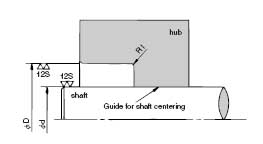
The AS Series POWER-LOCK is not self-aligning. Thus centering portion must be performed. Suggested "guide length" is to equal to or greater than one half of the shaft diameter.
If precise centering is required, design to have longer guide length and tight tolerance between shaft and hub.

STEP 3 Confirm machining tolerance and sureface roughness
Machining tolerance for counter bore diameter of hub "D" and shaft diameter "d " are listed on below table. Required surface roughness of 3.2 Ra. Determine the tolerance of the guide according to the centering accuracy required.
Standard tolerance table
Size of shaft or bore |
For Shaft |
For Bore |
3 < (d or D) ≤ 6 |
+ 0 - 0.018 |
+ 0.018 - 0 |
6 < (d or D) ≤ 10 |
+ 0 - 0.022 |
+ 0.022 - 0 |
10 < (d or D) ≤ 18 |
+ 0 - 0.027 |
+ 0.027 - 0 |
18 < (d or D) ≤ 30 |
+ 0 - 0.033 |
+ 0.033 - 0 |
30 < (d or D) ≤ 50 |
+ 0 - 0.039 |
+ 0.039 - 0 |
50 < (d or D) ≤ 80 |
+ 0 - 0.046 |
+ 0.046 - 0 |
80 < (d or D) ≤ 120 |
+ 0 - 0.054 |
+ 0.054 - 0 |
120 < (d or D) ≤ 180 |
+ 0 - 0.063 |
+ 0.063 - 0 |
180 < (d or D) ≤ 250 |
+ 0 - 0.072 |
+ 0.072 - 0 |
250 < (d or D) ≤ 315 |
+ 0 - 0.081 |
+ 0.081 - 0 |
315 < (d or D) ≤ 400 |
+ 0 - 0.089 |
+ 0.089 - 0 |
400 < (d or D) ≤ 500 |
+0 -0.097 |
+ 0.097 - 0 |
* Special tolerance for KE series
Only KE series Can be used for wider tolerance of shaft as below. When you apply special tolerance, transmissible toque Mt and thrust Pax will be 90% of the rating in the KE series specification table (page12).
Machining tolerance of the shaft for KE Series
Size of shaft or bore |
For Shaft |
For Bore |
3 < (d or D) ≤ 6 |
+ 0.012 - 0.018 |
- 0.018 - 0 .048 |
6 < (d or D) ≤ 10 |
+ 0.015 - 0.022 |
-0.022 - 0 .048 |
10 < (d or D) ≤ 18 |
+ 0 - 0.027 |
- 0.027 - 0 .070 |
18 < (d or D) ≤ 30 |
+ 0.021 - 0.033 |
- 0.033 - 0 .084 |
30 < (d or D) ≤ 50 |
+ 0.025 - 0.039 |
- 0.039 - 0.100 |
50 < (d or D) ≤ 80 |
+ 0.030 - 0.046 |
- 0.046 - 0.120 |
80 < (d or D) ≤ 120 |
+ 0.035 - 0.054 |
- 0.054 - 0.140 |
Bore size must be within the number listed on standard tolerance table
* Special tolerance for AS series
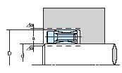
In cases where a slightly larger tolerance is required, the table below can be used. To use this table, it is important to understand that the goal is to have the POWER-LOCK centered in the middle of machined opening (i.e. : Δa = Δa).
Under these conditions the POWER-LOCK will transmit the published torque figures.

d = nominal I.D.
D = nominal O.D.
Δa deviation increment from nominal size
Note : When you specify shaft dimension,
d- Δa must be considered with D + Δa
d- Δa must be considered with D - Δa
Special tolerance for AS series
Size of shaft or bore |
For Shaft |
For Bore |
3 < (d or D) ≤ 6 |
+ 0 - 0.018 |
+ 0.018 - 0 |
6 < (d or D) ≤ 10 |
+ 0 - 0.022 |
+ 0.022 - 0 |
10 < (d or D) ≤ 18 |
+ 0 - 0.027 |
+ 0.027 - 0 |
18 < (d or D) ≤ 30 |
+ 0 - 0.033 |
+ 0.033 - 0 |
30 < (d or D) ≤ 50 |
+ 0 - 0.039 |
+ 0.039 - 0 |
50 < (d or D) ≤ 80 |
+ 0 - 0.046 |
+ 0.046 - 0 |
80 < (d or D) ≤ 120 |
+ 0 - 0.054 |
+ 0.054 - 0 |
120 < (d or D) ≤ 180 |
+ 0 - 0.063 |
+ 0.063 - 0 |
180 < (d or D) ≤ 250 |
+ 0 - 0.072 |
+ 0.072 - 0 |
250 < (d or D) ≤ 315 |
+ 0 - 0.081 |
+ 0.081 - 0 |
315 < (d or D) ≤ 400 |
+ 0 - 0.089 |
+ 0.089 - 0 |
400 < (d or D) ≤ 500 |
+0 -0.097 |
+ 0.097 - 0 |
