>> SELECTION GUIDE & SPECIFICATIONS
1. Determination of Maximum Torque and Thrust Load
Maximum torque and thrust load should be calculated or determined with safety factor.
* T max = 30000 x H x s.f.
![]() x n
x n
* P max = Pax x s.f.
Tmax : Maximum torque (N.m)
Pmax : Maximum thrust load (N)
H : Transmitting capacity (kW)
n : Revolution at the POWER-LOCK shaft (r/min)
s.f. : Safaty factor (Refer to the table below)
Condition of load |
Safety Factor |
|
No shock load |
Low inertia |
1.5 - 2.5 |
Moderate shock load |
Medium inertia |
2.0 - 4.0 |
Heavy shock load |
Big inertia |
3.0 - 5.0 |
When torque and thrust are applied at same time :
Compare (Mt) with composite torque (Mr)

d : Outside diameter of shaft (m)
Compare the maximum transmitting torque (Tmax) or composite torque (Mr) of the devices to be driven with the transmissible torque (Mt) of the POWER-LOCK listed on page of selected series.
* Mt ≥ Tmax or Mr - Good
* Mt < Tmax or Mr - Good
Select a larger POWER-LOCK or
use two or more POWR-LOCKs
Use multiple POWER-LOCK is available depend on the series of POWER-LOCK. The transmissible torque Mt of multiple POWER-LOCKs is obtained by multiplying Mt by the multiplier in the below table. Peak torque expected should be regarded as Tmax.
Table 1 Multiplier for Multiple use by series
Quantity |
1 |
2 |
3 |
4 |
As Series |
1 |
2 |
3 |
4 |
TF Series |
1 |
2 |
NG |
NG |
AE, KE EF Series |
1 |
NG |
NG |
NG |
2. Selection of POWER-LOCK by Series
STEP 1 Confirm for shaft and hub
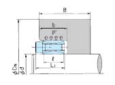
(1) Confirm the material strength When locking, big contact pressure will occur on shaft and hub. Confirm the yield point of shaft and hub using the following formula
* ![]() 0.2S ≥ K2 x P,
0.2S ≥ K2 x P, ![]() 0.2B ≥ K2 x P',
0.2B ≥ K2 x P',
P : Contact pressure on shaft (Mpa)
P' : Contact pressure on hub (MPa)
![]() 0.2S : Yield point of shaft material (MPa)
0.2S : Yield point of shaft material (MPa)
![]() 0.2B : Yield point of hub material (MPa)
0.2B : Yield point of hub material (MPa)
K2 : Series factor (Refer below table)
Name of Series |
Series Factor |
AS, TF |
1.4 |
AE, KE, EF |
1.2 |
(2) Confirm hub diameter
Refer the table for minimum hub diameter in each series. If the yield point is not shown in the table, calculate hub diameter uisng the following formula (not applicable to non-ferrous metals)

Dn : Minimum hub diameter (mm)
D : Inside diameter of hub bore (mm)
K3 : Hub geometry factor (Refer the table for minimum hub diameter in each series)
dG : Applicable for EF Series only Nominal diameter of locking bolt (mm)

(3) Confirm inside diameter of hollow shaft
When using hollow shaft, calculate inside diameter of the hollow shaft using the following formula

dB : Inside diameter of the hollow shaft (mm)
d : Outside diameter of shaft (mm)
