>> TSUBAKI POWER - LOCK AS Series
Features
-
Standard Type
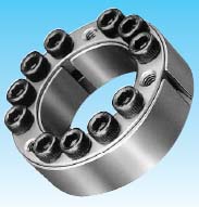
As Series is most popular type in the world. Stainless type is also available.
-
Eliminate Costly Machining
There is no need for time-consuming machining of keyways. The POWER-LOCK offers substantial savings on long, heavy shafts.
-
Easy Assembly And Disassembly
The POWER-LOCK can be assembled and disassembled frequently, so maintenance or replacement of worn part is simple and easy as compared to other methods (key and keyway,spline, shrink or press fits, and welding).


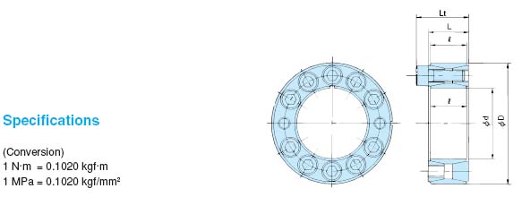
Specifications
(Conversion)
1 N.m = 0.1020 kgf.m
1 MPa = 0.1020 kgf/mm2
Model Number |
Dimensions (mm) |
Tansmissible Torque |
Thrust |
Contact Pressure |
Locking Bolts |
Mass |
||||||||||
Mt |
Pax |
Shaft P |
Hub bore P' |
Tightening Torque Ma |
||||||||||||
d x D Inside Dia Outside Dia |
L |
Lt |
N-m |
{Kgf-m} |
kN |
{kgf} |
MPa |
{kgf/mm2 |
MPa |
{kgf/mm2 |
Qty |
Size |
N-m |
{kgf-m} |
{kg} |
|
PL 019 x 047 |
20 |
18 |
26 |
245 |
{ 25} |
26.5 |
{ 2700} |
210 |
{ 21.4} |
85 |
{ 8.7} |
6 |
M6 x 18 |
16.7 |
1.7 |
0.20 |
PL 020 x 047 |
20 |
18 |
26 |
265 |
{ 27} |
26.5 |
{ 2700} |
199 |
{ 20.3} |
85 |
{ 8.7} |
6 |
M6 x 18 |
16.7 |
1.7 |
0.20 |
PL 022 x 047 |
20 |
18 |
26 |
294 |
{ 30} |
26.5 |
{ 2700} |
181 |
{ 18.5} |
85 |
{ 8.7} |
6 |
M6 x 18 |
16.7 |
1.7 |
0.19 |
PL 024 x 050 |
20 |
18 |
26 |
402 |
{ 41} |
33.3 |
{ 3400} |
211 |
{ 21.5} |
101 |
{10.3} |
8 |
M6 x 18 |
16.7 |
1.7 |
0.22 |
PL 025 x 050 |
20 |
18 |
26 |
421 |
{ 43} |
33.3 |
{ 3400} |
203 |
{ 20.7} |
101 |
{10.3} |
8 |
M6 x 18 |
16.7 |
1.7 |
0.22 |
PL 028 x 055 |
20 |
18 |
26 |
470 |
{ 48} |
33.3 |
{ 3400} |
180 |
{ 184.4} |
92 |
{ 9.4} |
8 |
M6 x 18 |
16.7 |
1.7 |
0.25 |
PL 030 x 055 |
20 |
18 |
26 |
510 |
{ 52} |
33.3 |
{ 3400} |
169 |
{ 17.2} |
92 |
{ 9.4} |
8 |
M6 x 18 |
16.7 |
1.7 |
0.24 |
PL 032 x 060 |
20 |
18 |
26 |
676 |
{ 69} |
42.1 |
{ 4300} |
198 |
{ 20.2} |
106 |
{ 10.8} |
10 |
M6 x 18 |
16.7 |
1.7 |
0.27 |
PL 035 x 060 |
20 |
18 |
26 |
745 |
{ 76} |
42.1 |
{ 4300} |
181 |
{ 18.5} |
106 |
{ 10.8} |
10 |
M6 x 18 |
16.7 |
1.7 |
0.27 |
PL 038 x 065 |
20 |
18 |
26 |
892 |
{ 91} |
47.0 |
{ 4800} |
183 |
{ 18.7} |
107 |
{ 10.9} |
11 |
M6 x 18 |
16.7 |
1.7 |
0.30 |
PL 040 x 065 |
20 |
18 |
26 |
941 |
{ 96} |
47.0 |
{ 4800} |
174 |
{ 17.8} |
107 |
{10.9} |
11 |
M6 x 18 |
16.7 |
1.7 |
0.30 |
PL 042 x 075 |
24 |
21 |
32 |
1490 |
{ 152} |
70.6 |
{ 7200} |
214 |
{ 21.8} |
121 |
{12.3} |
9 |
M8 x 22 |
40.2 |
4.1 |
0.51 |
PL 045 x 075 |
24 |
21 |
32 |
1600 |
{ 163} |
70.6 |
{ 7200} |
200 |
{ 20.4} |
121 |
{12.3} |
9 |
M8 x 22 |
40.2 |
4.1 |
0.51 |
PL 048 x 080 |
24 |
21 |
32 |
1700 |
{ 173} |
70.6 |
{ 7200} |
188 |
{ 19.2} |
113 |
{11.5} |
9 |
M8 x 22 |
40.2 |
4.1 |
0.55 |
PL 050 x 080 |
24 |
21 |
32 |
1770 |
{ 181} |
70.6 |
{ 7200} |
180 |
{ 18.4} |
113 |
{11.5} |
9 |
M8 x 22 |
40.2 |
4.1 |
0.55 |
PL 055 x 085 |
24 |
21 |
32 |
2390 |
{ 244} |
86.2 |
{ 8800} |
201 |
{ 20.5} |
130 |
{13.3} |
11 |
M8 x 22 |
40.2 |
4.1 |
0.60 |
PL 060 x 090 |
24 |
21 |
32 |
2610 |
{ 266} |
86.2 |
{ 8800} |
184 |
{ 18.8} |
123 |
{12.5} |
11 |
M8 x 22 |
40.2 |
4.1 |
0.64 |
PL 065 x 095 |
24 |
21 |
32 |
3090 |
{ 315} |
94.1 |
{ 9600} |
184 |
{ 18.8} |
126 |
{12.9} |
12 |
M8 x 22 |
40.2 |
4.1 |
0.69 |
PL 070 x 110 |
28 |
25 |
38 |
4800 |
{ 490} |
138 |
{ 14100} |
210 |
{ 21.4} |
133 |
{13.6} |
11 |
M10 x 25 |
81.3 |
81.3 |
1.21 |
PL 075 x 115 |
28 |
25 |
38 |
5190 |
{ 530} |
138 |
{ 14100} |
196 |
{ 20.0} |
127 |
{13.0} |
11 |
M10 x 25 |
81.3 |
81.3 |
1.27 |
PL 080 x 120 |
28 |
25 |
38 |
5490 |
{ 560} |
138 |
{ 14100} |
184 |
{18.8} |
123 |
{12.5} |
11 |
M10 x 25 |
81.3 |
8.3 |
1.33 |
PL 085 x 125 |
28 |
25 |
38 |
6370 |
{ 650} |
150 |
{ 15300} |
189 |
{19.3} |
128 |
{13.1} |
12 |
M10 x 25 |
81.3 |
8.3 |
1.41 |
PL 090 x 130 |
28 |
25 |
38 |
6760 |
{ 690} |
150 |
{ 15300} |
178 |
{18.2} |
123 |
{12.6} |
12 |
M10 x 25 |
81.3 |
8.3 |
1.47 |
PL 095 x 135 |
28 |
25 |
38 |
7740 |
{ 790} |
163 |
{ 16600} |
183 |
{18.7} |
129 |
{13.2} |
13 |
M10 x 25 |
81.3 |
8.3 |
1.54 |
PL 100 x 145 |
33 |
29 |
45 |
10000 |
{ 1020} |
201 |
{ 20500} |
184 |
{18.8} |
127 |
{13.0} |
11 |
M12 x 30 |
142 |
14.5 |
2.09 |
PL 110 x 155 |
33 |
29 |
45 |
11100 |
{ 1130} |
201 |
{ 20500} |
168 |
{17.1} |
120 |
{12.2} |
11 |
M12 x 30 |
142 |
14.5 |
2.25 |
PL 120 x 165 |
33 |
29 |
45 |
13100 |
{ 1340} |
202 |
{ 22400} |
168 |
{17.1} |
123 |
{12.5} |
12 |
M12 x 30 |
142 |
14.5 |
2.42 |
PL 130 x 180 |
38 |
34 |
50 |
17800 |
{ 1820} |
274 |
{ 28000} |
166 |
{16.9} |
120 |
{12.2} |
15 |
M12 x 35 |
142 |
14.5 |
3.38 |
PL 140 x 190 |
38 |
34 |
50 |
20500 |
{ 2090} |
292 |
{ 29800} |
164 |
{16.7} |
121 |
{12.3} |
16 |
M12 x 35 |
142 |
14.5 |
3.59 |
PL 150 x 200 |
38 |
34 |
50 |
24700 |
{ 2520} |
329 |
{33600} |
172 |
{17.5} |
129 |
{13.2} |
18 |
M12 x 35 |
142 |
14.5 |
3.82 |
PL 160 x 210 |
38 |
34 |
50 |
27700 |
{ 2830} |
347 |
{35400} |
170 |
{17.3} |
129 |
{13.2} |
19 |
M12 x 35 |
142 |
14.5 |
4.03. |
PL 170 x 225 |
44 |
40 |
58 |
34100 |
{ 3480} |
402 |
{41000} |
157 |
{16.0} |
119 |
{12.1} |
16 |
M14 x 40 |
225 |
23.0 |
5.49 |
PL 180 x 235 |
44 |
40 |
58 |
38400 |
{ 3920} |
426 |
{43500} |
158 |
{16.1} |
121 |
{12.3} |
17 |
M14 x 40 |
225 |
23.0 |
5.78 |
PL 190 x 250 |
52 |
48 |
66 |
47600 |
{ 4860} |
502 |
{51200} |
147 |
{15.0} |
112 |
{11.4} |
20 |
M14 x 45 |
225 |
23.0 |
7.89 |
PL 200 x 260 |
52 |
48 |
66 |
52700 |
{53800} |
527 |
{53800} |
146 |
{14.9} |
113 |
{11.5} |
21 |
M14 x 45 |
225 |
23.0 |
8.26 |
PL 220 x 285 |
56 |
51 |
72 |
69100 |
{ 7050} |
628 |
{ 64100} |
149 |
{15.2} |
115 |
{11.7} |
18 |
M16 x 50 |
348 |
35.5 |
10.6 |
PL 240 x 305 |
56 |
51 |
72 |
83800 |
{ 8550} |
698 |
{ 71200} |
152 |
{15.5} |
120 |
{12.2} |
20 |
M16 x 50 |
348 |
35.5 |
11.5 |
PL 260 x 325 |
56 |
51 |
72 |
104000 |
{ 10600} |
803 |
{ 81900} |
161 |
{16.4} |
129 |
{13.2} |
23 |
M16 x 50 |
348 |
35.5 |
12.4 |
PL 280 x 355 |
66 |
61 |
84 |
129000 |
{ 13200} |
923 |
{ 94200} |
144 |
{14.7} |
114 |
{11.6} |
22 |
M18 x 60 |
475 |
48.5 |
18.7 |
PL 300 x 375 |
66 |
61 |
84 |
151000 |
{ 15400} |
1000 |
{102000} |
147 |
{15.0} |
118 |
{12.0} |
24 |
M18 x 60 |
475 |
48.5 |
19.9 |
Note :-
- Torque Mt in above table is shown in case of Pax=0 and thrust Pax is shown n case of Mt=0 When torque and thrust are applied calculate composite torque and compare it with Mt.
-
Contact pressure P and P' in the above table indicate mean value only.
These pressures will fluctuate from - 20% to +40% due to the variable friction component forces resulting from the locking bolts. Mt and Pax are calculated as minimum values.
