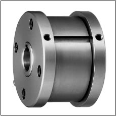
>> MZEU-K SERIES CAM CLUTCHES
E1+E2

.jpg)
Dimensions and Capacity
Dimensions in mm
Model |
Torque Capacity |
Max. Overrunnig Speed |
Drag Torque |
Bore Size |
Keyway |
A |
B |
BF |
C |
D |
F |
L |
M |
b |
t1 |
Weight |
|
Inner Race |
Outer Race |
||||||||||||||||
N.m |
r/min |
r/min |
N.m |
H7 |
h7 |
C |
P10 |
kg |
|||||||||
MZEU12K E5 + E5 |
60 |
2000 |
1000 |
0.20 |
12 |
4 x 1.8 |
42 |
62 |
70 |
20 |
51 |
20 |
0.8 |
10.0 |
4 |
2.5 |
0.5 |
MZEU15K E5 + E5 |
100 |
1800 |
900 |
0.20 |
15 |
5 x 2.3 |
52 |
68 |
76 |
28 |
56 |
25 |
0.8 |
11.0 |
5 |
3.0 |
0.8 |
MZEU20K E5 + E5 |
245 |
1600 |
700 |
0.29 |
20 |
6 x 2.8 |
57 |
75 |
84 |
34 |
64 |
30 |
0.8 |
10.5 |
6 |
3.5 |
1.2 |
MZEU25K E5 + E5 |
425 |
1600 |
600 |
0.33 |
25 |
8 x 3.3 |
60 |
90 |
99 |
35 |
78 |
40 |
0.8 |
11.5 |
8 |
4.0 |
1.8 |
MZEU30K E5 + E5 |
735 |
1500 |
500 |
0.39 |
30 |
8 x 3.3 |
68 |
100 |
109 |
43 |
87 |
45 |
1.0 |
11.5 |
8 |
4.0 |
2.6 |
MZEU35K E5 + E5 |
1015 |
1400 |
300 |
0.49 |
35 |
10 x 3.3 |
74 |
110 |
119 |
45 |
96 |
50 |
1.0 |
13.5 |
10 |
5.0 |
3.2 |
MZEU40K E5 + E5 |
1350 |
1400 |
300 |
0.59 |
40 |
12 x 3.3 |
86 |
125 |
135 |
53 |
108 |
55 |
1.3 |
15.5 |
12 |
5.0 |
4.8 |
MZEU45K E5 + E5 |
1620 |
1400 |
300 |
0.69 |
45 |
14 x 3.8 |
86 |
130 |
140 |
53 |
112 |
60 |
1.3 |
15.5 |
14 |
5.5 |
6.2 |
MZEU50KE5 + E5 |
2070 |
1300 |
250 |
0.79 |
50 |
14 x 3.8 |
94 |
150 |
160 |
64 |
132 |
70 |
1.3 |
14.0 |
14 |
5.5 |
8.2 |
MZEU55K E5 + E5 |
2400 |
1300 |
250 |
0.88 |
55 |
16 x 4.3 |
104 |
160 |
170 |
66 |
138 |
75 |
1.5 |
18.0 |
16 |
6.0 |
9.5 |
MZEU60K E5 + E5 |
2950 |
1200 |
250 |
0.98 |
60 |
18 x 4.4 |
114 |
170 |
182 |
78 |
150 |
80 |
1.5 |
17.0 |
18 |
7.0 |
12.3 |
MZEU70K E5 + E5 |
4210 |
1100 |
250 |
1.27 |
70 |
20 x 4.9 |
134 |
190 |
202 |
95 |
165 |
90 |
1.8 |
18.5 |
20 |
7.5 |
18.1 |
MZEU80K E5 + E5 |
5170 |
800 |
200 |
1.38 |
80 |
22 x 5.4 |
144 |
210 |
222 |
100 |
185 |
105 |
1.8 |
21.0 |
22 |
9.0 |
23.1 |
MZEU 90 E5 + E5 |
12000 |
450 |
150 |
4.70 |
90 |
25 x 5.4 |
158 |
230 |
242 |
115 |
206 |
120 |
2.0 |
20.5 |
25 |
9.0 |
28.1 |
MZEU100E5 + E5 |
17600 |
400 |
130 |
5.39 |
100 |
28 x 6.4 |
182 |
270 |
282 |
120 |
240 |
140 |
2.0 |
30.0 |
28 |
10.0 |
46.3 |
MZEU 130 E5 + E5 |
24500 |
320 |
110 |
6.76 |
130 |
32 x 7.4 |
212 |
310 |
322 |
152 |
278 |
160 |
2.5 |
29.0 |
32 |
11.0 |
70.2 |
MZEU 150 E5 + E5 |
33800 |
240 |
80 |
8.13 |
150 |
36 x 8.4 |
246 |
400 |
412 |
180 |
360 |
200 |
2.5 |
32.0 |
36 |
12.0 |
146.3 |
Installation and Usage
- The clutch is delivered with a Basic type Cam Clutch, two E5 flanges, and flange kit as separate parts.
- Check the direction of rotation and attach an E5 flange to the clutch by the bolt.
- When installing sprocket, gear and other equipment to the clutch, install them on the outer race and fix the key between the equipment and the outer race.
- We recommend a tolerance of H7 for the bore of the sprocket, gear or other equipment.
- Attach the opposite side E5 flange to the clutch by the bolts.
- By installing the clutch to the shaft on the opposite side, the direction of rotation can be changed.
- When mounting the clutch onto the shaft, apply pressure to the inner race but never to the outer race.
- For high speed indexing application (More than 50 c/min) a strong spring type is recommended.
.jpg)
