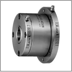
>> MZEU-K SERIES CAM CLUTCHES
E1+E2

.jpg)
Dimensions and Capacity
Dimensions in mm
Model |
Torque Capacity |
Max. Overrunnig Speed |
Drag Torque |
Bore Size |
Keyway |
A |
B |
BF |
C |
DF |
F |
L |
M |
N |
O-P |
Weight |
|
Inner Race |
Outer Race |
||||||||||||||||
N.m |
r/min |
r/min |
N.m |
H7 |
h7 |
C |
3-Ø5.5 |
kg |
|||||||||
MZEU12K E1+E2 |
60 |
2000 |
1000 |
0.20 |
12 |
4 x 1.8 |
42 |
62 |
85 |
20 |
72 |
20 |
0.8 |
10.0 |
5.7 |
3-Ø5.5 |
1.1 |
MZEU15K E1+E2 |
100 |
1800 |
900 |
0.20 |
15 |
5 x 2.3 |
52 |
68 |
92 |
28 |
78 |
25 |
0.8 |
11.0 |
5.7 |
4-Ø5.5 |
1.5 |
MZEU20K E1 + E2 |
245 |
1600 |
700 |
0.29 |
20 |
6 x 2.8 |
57 |
75 |
98 |
34 |
85 |
30 |
0.8 |
10.5 |
5.7 |
4-Ø5.5 |
1.9 |
MZEU25K E1 + E2 |
425 |
1600 |
600 |
0.33 |
25 |
8 x 3.3 |
60 |
90 |
118 |
35 |
104 |
40 |
0.8 |
11.5 |
6.8 |
6-Ø6.6 |
2.9 |
MZEU30K E1 + E2 |
735 |
1500 |
500 |
0.39 |
30 |
8 x 3.3 |
68 |
100 |
128 |
43 |
114 |
45 |
1.0 |
11.5 |
6.8 |
6-Ø6.6 |
4.0 |
MZEU35K E1 + E2 |
1015 |
1400 |
300 |
0.49 |
35 |
10 x 3.3 |
74 |
110 |
140 |
45 |
124 |
50 |
1.0 |
13.5 |
6.8 |
6-Ø6.6 |
5.2 |
MZEU40K E1 + E2 |
1350 |
1400 |
300 |
0.59 |
40 |
12 x 3.3 |
86 |
125 |
160 |
53 |
142 |
55 |
1.3 |
15.5 |
9.0 |
8-Ø9.0 |
7.9 |
MZEU45K E1 + E2 |
1620 |
1400 |
300 |
0.69 |
45 |
14 x 3.8 |
86 |
130 |
165 |
53 |
146 |
60 |
1.3 |
15.5 |
9.0 |
8-Ø9.0 |
9.3 |
MZEU50K E1 + E2 |
2070 |
1300 |
250 |
0.79 |
50 |
14 x 3.8 |
94 |
150 |
185 |
64 |
166 |
70 |
1.3 |
14.0 |
9.0 |
8-Ø9.0 |
11.7 |
MZEU55K E1 + E2 |
2400 |
1300 |
250 |
0.88 |
55 |
16 x 4.3 |
104 |
160 |
204 |
66 |
182 |
75 |
1.5 |
18.0 |
11.0 |
10-Ø11.0 |
15.3 |
MZEU60K E1 + E2 |
2950 |
1200 |
250 |
0.98 |
60 |
18 x 4.4 |
114 |
170 |
214 |
78 |
192 |
80 |
1.5 |
17.0 |
11.0 |
10-Ø11.0 |
17.7 |
MZEU70K E1 + E2 |
4210 |
1100 |
250 |
1.27 |
70 |
20 x 4.9 |
134 |
190 |
234 |
95 |
212 |
90 |
1.8 |
18.5 |
11.0 |
10-Ø11.0 |
25.5 |
MZEU80K E1 + E2 |
5170 |
800 |
200 |
1.38 |
80 |
22 x 5.4 |
144 |
210 |
254 |
100 |
232 |
105 |
1.8 |
21.0 |
11.0 |
10-Ø11.0 |
33.2 |
MZEU 90 E1 + E2 |
12000 |
450 |
150 |
4.70 |
90 |
25 x 5.4 |
158 |
230 |
278 |
115 |
254 |
120 |
2.0 |
20.5 |
13.0 |
14-Ø14.0 |
38.3 |
MZEU100E1 + E2 |
17600 |
400 |
130 |
5.39 |
100 |
28 x 6.4 |
182 |
270 |
335 |
120 |
305 |
140 |
2.0 |
30.0 |
17.5 |
10-Ø18.0 |
68.8 |
MZEU 130 E1 + E2 |
24500 |
320 |
110 |
6.76 |
130 |
32 x 7.4 |
212 |
310 |
380 |
152 |
345 |
160 |
2.5 |
29.0 |
17.5 |
12-Ø18.0 |
98.2 |
MZEU 150 E1 + E2 |
33800 |
240 |
80 |
8.13 |
150 |
36 x 8.4 |
246 |
400 |
485 |
180 |
445 |
200 |
2.5 |
32.0 |
21.5 |
12-Ø22.0 |
198.2 |
Installation and Usage
- The clutch is delivered with a Basic type Cam Clutch, E1 flange, E1 flange and each flange kit as separate parts.
- Check the direction of rotation and attach the each flange to the clutch.
- When installing sprocket, gear and other equipment to the clutch, fit them on the surface of the outer race of rlange and screw the bolt into them.
- By installing both option parts on the opposite side, the direction of rotation can be changed.
- When mounting the clutch onto the shaft, apply pressure to the inner race but never to the outer race.
- For high speed indexing application (More than 50 c/min) a strong spring type is recommended.
.jpg)
