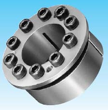
>> TSUBAKI POWER - LOCK AE Series
Features
-
Self - Centering Function
Straight and narrow hubs can be used with AE Series POWER-LOCK.
-
Interchangeable POWER-LOCK AS Series to AE Series
Have the same size inside diameter and outside diameter as POWER-LOCK AS Series.
-
Easy and Precise Positioning
-
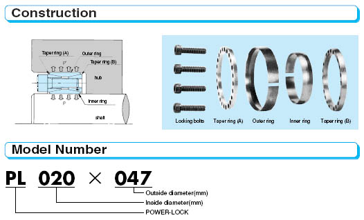
Simple Construction


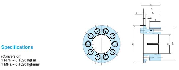
Specifications
(Conversion)
1 N.m = 0.1020 kgf.m
1 MPa = 0.1020 kgf/mm2
Model |
Dimensions (mm) |
Transmissible Torque |
Transmissible Thrust |
Contact Pressure (Mpa) |
Locking Bolts |
Mass |
||||||||||||||
d x D Inside Dia Outside Dia |
l |
L2 |
L |
Lt |
t1 |
t2 |
D1 |
Mt |
Pax |
Shaft P |
Hub bore P' |
Qty |
Size |
Tightening Torque Ma |
(kg) |
|||||
N-m |
{kgf-m} |
kN |
{kgf} |
MPa |
kgf/mm2 |
MPa |
kgf/mm2 |
N-m |
{kgf-m} |
|||||||||||
PL 019 x 047 AE |
19 |
24.8 |
27.3 |
33.3 |
2.5 |
3 |
53 |
265 |
{ 27} |
28.1 |
{2870} |
287 |
{29.3} |
93 |
{9.5} |
6 |
M6 x18 |
16.7 |
{1.7} |
0.28 |
PL 020 x 047 AE |
19 |
24.8 |
27.3 |
33.3 |
2.5 |
3 |
53 |
274 |
{ 28} |
28.1 |
{2870} |
272 |
{27.8} |
93 |
{9.5} |
6 |
M6 x18 |
16.7 |
{1.7} |
0.27 |
PL 022 x 047 AE |
19 |
24.8 |
27.3 |
33.3 |
2.5 |
3 |
53 |
304 |
{ 31} |
28.1 |
{2870} |
248 |
{25.3} |
93 |
{9.5} |
6 |
M6 x18 |
16.7 |
{1.7} |
0.26 |
PL 024 x 050 AE |
19 |
25.3 |
27.8 |
33.8 |
2.5 |
3 |
57 |
392 |
{ 40} |
32.8 |
{3350} |
274 |
{28.0} |
102 |
{10.4} |
7 |
M6 x18 |
16.7 |
{1.7} |
0.29 |
PL 025 x 050 AE |
19 |
25.3 |
27.8 |
33.8 |
2.5 |
3 |
57 |
412 |
{ 42} |
32.8 |
{3350} |
282 |
{28.8} |
102 |
{10.4} |
7 |
M6x18 |
16.7 |
{1.7} |
0.29 |
PL 028 x 055 AE |
19 |
25.3 |
28.6 |
34.6 |
3.3 |
3 |
62 |
519 |
{ 53} |
37.5 |
{3830} |
269 |
{27.4} |
106 |
{10.8} |
8 |
M6x18 |
16.7 |
{1.7} |
0.35 |
PL 030 x 055 AE |
19 |
25.3 |
28.6 |
34.6 |
3.3 |
3 |
62 |
559 |
{ 57} |
37.5 |
{3830} |
251 |
{25.6} |
106 |
{10.8} |
8 |
M6x18 |
16.7 |
{1.7} |
0.34 |
PL 032 x 060 AE |
20.5 |
27.3 |
30.9 |
36.9 |
3.6 |
3 |
67 |
745 |
{ 76} |
46.9 |
{4790} |
267 |
{27.2} |
113 |
{11.5} |
10 |
M6x18 |
16.7 |
{1.7} |
0.44 |
PL 035 x 060 AE |
20.5 |
27.3 |
30.9 |
36.9 |
3.6 |
3 |
67 |
823 |
{ 84} |
46.9 |
{4790} |
244 |
{24.9} |
113 |
{11.5} |
10 |
M6x18 |
16.7 |
{1.7} |
0.41 |
PL 038 x 065 AE |
20.5 |
27.5 |
31.1 |
37.1 |
3.6 |
3 |
73 |
892 |
{ 91} |
46.9 |
{4790} |
228 |
{23.3} |
104 |
{10.6} |
10 |
M6x18 |
16.7 |
{1.7} |
0.48 |
PL 040 x 065 AE |
20.5 |
27.5 |
31.1 |
37.1 |
3.6 |
3 |
73 |
931 |
{ 95} |
46.9 |
{4790} |
217 |
{22.1} |
104 |
{10.6} |
10 |
M6x18 |
16.7 |
{1.7} |
0.45 |
PL 042 x 075 AE |
23.5 |
30.8 |
34.8 |
42.8 |
4 |
3 |
83 |
1640 |
{ 167} |
78.1 |
{7970} |
285 |
{29.1} |
130 |
{13.3} |
9 |
M8x22 |
40.2 |
{4.1} |
0.76 |
PL 045 x 075 AE |
23.5 |
30.8 |
34.8 |
42.8 |
4 |
3 |
83 |
1750 |
{ 179} |
78.1 |
{7970} |
266 |
{27.1} |
130 |
{13.3} |
9 |
M8x22 |
40.2 |
{4.1} |
0.71 |
PL 048 x 080 AE |
23.5 |
31.0 |
35 |
43 |
4 |
3 |
88 |
2060 |
{ 210} |
86.8 |
{8860} |
280 |
{28.6} |
136 |
{13.9} |
10 |
M8x22 |
40.2 |
{4.1} |
0.81 |
PL 050 x 080 AE |
23.5 |
31.0 |
35 |
43 |
4 |
3 |
88 |
2160 |
{ 220} |
86.8 |
{8860} |
270 |
{27.5} |
136 |
{13.9} |
10 |
M8x22 |
40.2 |
{4.1} |
0.77 |
PL 055 x 085 AE |
23.5 |
30.8 |
34.8 |
42.8 |
4 |
3 |
94 |
2350 |
{240} |
86.8 |
{8860} |
242 |
{24.7} |
128 |
{13.1} |
10 |
M8x22 |
40.2 |
{4.1} |
0.84 |
PL 060 x 090 AE |
23.5 |
30.8 |
34.8 |
42.8 |
4 |
3 |
99 |
2550 |
{260} |
86.8 |
{8860} |
219 |
{22.3} |
122 |
{12.4} |
10 |
M8x22 |
40.2 |
{4.1} |
0.90 |
PL 065 x 095 AE |
23.5 |
30.8 |
34.8 |
42.8 |
4 |
3 |
104 |
3330 |
{340} |
104 |
{10600} |
246 |
{25.1} |
137 |
{14.0} |
12 |
M8x22 |
40.2 |
{4.1} |
0.96 |
PL 070 x 110 AE |
28 |
36.5 |
41 |
51 |
4.5 |
4 |
120 |
4800 |
{490} |
137 |
{14000} |
247 |
{25.2} |
132 |
{13.5} |
10 |
M10x25 |
81.3 |
{8.3} |
1.70 |
PL 075 x 115 AE |
28 |
36.5 |
41 |
51 |
4.5 |
4 |
125 |
5100 |
{520} |
137 |
{14000} |
230 |
{23.5} |
126 |
{12.9} |
10 |
M10x25 |
81.3 |
{8.3} |
1.79 |
PL 080 x 120 AE |
28 |
36.5 |
41 |
51 |
4.5 |
4 |
130 |
6570 |
{ 670} |
165 |
{16800} |
260 |
{26.5} |
145 |
{14.8} |
12 |
M10x25 |
81.3 |
{8.3} |
1.89 |
PL 085 x 125 AE |
28 |
36.5 |
41 |
51 |
4.5 |
4 |
135 |
6960 |
{ 710} |
165 |
{16800} |
244 |
{24.9} |
139 |
{14.2} |
12 |
M10x25 |
81.3 |
{8.3} |
1.98 |
PL 090 x 130 AE |
28 |
37.5 |
43 |
53 |
5.5 |
4 |
140 |
7450 |
{760} |
165 |
{16800} |
241 |
{24.6} |
134 |
{13.7} |
12 |
M10x25 |
81.3 |
{8.3} |
2.15 |
PL 095 x 135 AE |
28 |
37.5 |
43 |
53 |
5.5 |
4 |
145 |
9110 |
{930} |
193 |
{19700} |
267 |
{27.2} |
151 |
{15.4} |
14 |
M10x25 |
81.3 |
{8.3} |
2.24 |
PL 100 x 145 AE |
34 |
44.0 |
50 |
60 |
6 |
4 |
155 |
10300 |
{1050} |
207 |
{21100} |
218 |
{22.2} |
123 |
{12.6} |
15 |
M10x25 |
81.3 |
{8.3} |
3.07 |
PL 110 x 155 AE |
34 |
44.0 |
50 |
60 |
6 |
4 |
167 |
11400 |
{1160} |
207 |
{21100} |
198 |
{20.2} |
116 |
{11.8} |
15 |
M10x25 |
81.3 |
{8.3} |
3.35 |
PL 120 x 165 AE |
34 |
44.0 |
50 |
60 |
6 |
4 |
177 |
14900 |
{1520} |
248 |
{25300} |
218 |
{22.2} |
130 |
{13.3} |
18 |
M10x25 |
81.3 |
{8.3} |
3.59 |
PL 130 x 180 AE |
38 |
50.0 |
57 |
69 |
7 |
6 |
195 |
19600 |
{2000} |
301 |
{30700} |
214 |
{21.8} |
129 |
{13.2} |
15 |
M12x35 |
142 |
{14.5} |
5.04 |
PL 140 x 190 AE |
38 |
50.0 |
57 |
69 |
7 |
6 |
205 |
21100 |
{2150} |
301 |
{30700} |
198 |
{20.2} |
123 |
{12.6} |
15 |
M12x35 |
142 |
{14.5} |
5.38 |
PL 150 x 200 AE |
38 |
50.0 |
58 |
70 |
8 |
6 |
215 |
27000 |
{2760} |
361 |
{36800} |
221 |
{22.6} |
140 |
{14.3} |
18 |
M12x35 |
142 |
{14.5} |
5.81 |
Note :-
- Torque Mt in above table is shown in case of Pax=0 and thrust Pax is shown n case of Mt=0 When torque and thrust are applied calculate composite torque and compare it with Mt.
-
Contact pressure P and P' in the above table indicate mean value only.
These pressures will fluctuate from - 20% to +40% due to the variable friction component forces resulting from the locking bolts. Mt and Pax are calculated as minimum values.
